
Dry-Hung Fiber Cement Cladding Installation Guide
Dry-Hung Fiber Cement Cladding Installation: Step-by-Step Guide
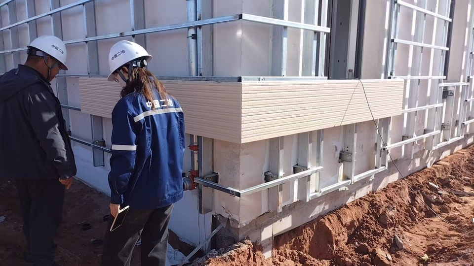
Dry-hung installation means the panel is carried by mechanical connectors over an open, drained cavity — never bonded to the wall. Six components do the work: the panel, a raised connector, a ventilation fixing metal piece, screws for the metal parts, screws for the foundation substrate, and a ventilated water baffle at the base. Get those six right and the sequence is straightforward. Get the sequence wrong and the facade leaks, drums, or both.
This guide follows the order we specify for a 3030 × 455 × 16 mm textured panel on a ventilated rainscreen, with the numbers that actually govern each step.
What "dry-hung" actually means, and why adhesive is not an option
A dry-hung facade separates three jobs that a bonded system fuses into one. The panel provides the weather skin and the appearance. The cavity behind it drains any water that gets past the joints and lets air move up the wall to dry it. The connectors transfer wind load from the panel to the structure while allowing the panel to move independently of the substrate.
Bonding collapses all three. A 26.9 kg panel set in adhesive cannot be removed without destroying it, so a single damaged course means cutting out a section and patching a joint that will never match. More importantly, an adhered panel has no drainage path: water that enters at a joint sits against the substrate, and the only exit is back out through the same joint. On a cement-based board that also absorbs 16.5% moisture by weight, that is a slow failure rather than a fast one — the wall looks fine for two or three years and then the coating blisters.
The mechanical system also lets the panel do what fiber cement does best: move. Moisture deformation is 0.05% and thermal movement is small but real. A hung panel moves on its connector; a bonded panel fights the substrate and loses.
The six components
| Component | What it does | What happens if it is wrong |
|---|---|---|
| External wall panel, 3030 × 455 × 16 mm | Weather skin and finish, 19.5 kg/m² | Thin or undersized panel deflects between fixings |
| Raised connector | Carries the panel and sets the cavity | Set out of plumb, the courses run out of level |
| Ventilation fixing metal piece | Ties adjacent panels and maintains the ventilation gap | Missing, the panels butt tight and the cavity closes |
| Special screws for metal pieces | Fix panel and connector together | Ordinary screws corrode or strip at the head |
| Special screws for foundation substrate | Anchor the connector to the structure | Anchoring into insulation instead of structure |
| Foundation water baffle | Holds the bottom edge clear of splash and forms the air inlet | Blocked by paving or soil, the whole cavity stops breathing |
Behind them sit three more layers that are not ours to supply but decide whether the system works: a water-resistive barrier, the insulation in the stud bay, and the substrate itself. The cavity must stay empty — it is a drainage and ventilation path, not a place to put insulation.
Step 1: Set out the 455 mm module before you fix anything
The 3030 × 455 × 16 mm panel is 3,030 mm long and 455 mm high, laid as a horizontal course, so the 455 mm dimension is the one that controls the whole elevation. Set out from a fixed datum at the base, run the module up the wall, and check where the courses land at the head, at every window head and sill, and at the parapet.
Three rules make the difference between a facade that reads as designed and one that looks improvised:
- Put the cut at the least visible point. Work the module so that partial courses land at the top of the wall or under a canopy, not at eye level above the entrance.
- Never leave a sliver. A strip under about 150 mm reads as a mistake and is difficult to fix securely. Shift the datum and let the top course take the adjustment.
- Check level across the full elevation, not per bay. A 1 mm error per bay accumulates into 10 mm over ten bays, and the eye picks up accumulated error far more readily than any single joint.
Mark the datum line on the substrate and carry it around corners with a laser or a water level. Everything after this step is measured from that line.
Step 2: Water-resistive barrier, cavity and insulation
The barrier goes on first, lapped in shingle fashion so water runs out and down, with laps and penetrations taped. It must be continuous behind the whole elevation, including behind the connector positions — a barrier interrupted at every bracket is not a barrier. Work from the bottom up, keep the upper sheet outside the lower one, and tape every lap and every penetration where a connector screw passes through. A barrier that is only stapled at the laps sheds water on the drawing and not on the wall.
Then the cavity. Twenty millimetres is the practical minimum for airflow; most detailing lands between 25 and 40 mm. The cavity is bounded by the barrier at the back and the panel at the front, open at the base and open at the head. Deeper is not automatically better — past about 40 mm the connectors start to cantilever further than they need to, and the wind load has more lever arm to work with.
Insulation belongs in the stud bay, behind the barrier. Putting mineral wool into the cavity itself blocks the airflow that the whole system depends on, and it holds water against the barrier when water does get in. Where extra insulation is needed, increase the stud depth or add a separate insulated sheathing layer — do not steal the cavity.
Photograph this stage before the panels go on. Once the facade is closed, the barrier is uninspectable, and any defect in it only surfaces as a damp patch two winters later, by which time the cause is a guess.
Step 3: Fix the raised connectors
Connectors run vertically and are fixed through the barrier into the substrate, at a spacing set by the project's wind load calculation. Two practical points govern quality here:
Plumb, not merely straight. A connector that is straight but out of plumb puts the panel in a slight twist, and the twist shows up as a wavy shadow line under raking light. Check with a level on every third connector at minimum.
Anchor into structure. The screw must reach framing or masonry, not the insulation face and not the sheathing alone. Pull-out values from a screw buried in foam are not pull-out values; the connector will creep under wind load and the joint will open.
Where panels meet end to end, the ventilation fixing metal piece bridges them and maintains the gap. These pieces are what stop the installer from pulling two panels tight together, and they are the component most often left in the van.
Step 4: Set the foundation water baffle at the base
The base detail does two things at once. It holds the bottom edge of the panel clear of splash and standing water, and it forms the air inlet for the cavity. A ventilated baffle does both; a solid flashing does the first and blocks the second.
Set it so the bottom edge of the lowest panel finishes above the finished ground level and above the paving or deck, with enough clearance that runoff cannot wick up into the board. On a wall that meets soil, that means the baffle sits above the damp-proof course, not buried behind landscaping.
This is the detail that fails most often in service, and it is almost always a site decision made after handover — a planter bed raised against the wall, a path laid 20 mm too high. Leave the clearance and write it on the drawing.
Two practical notes for the crew. First, the baffle is a permanent component, not temporary protection: do not remove it to make room for a threshold or a step, and do not let the groundworker lay paving tight to it to keep a line tidy. Second, if the wall meets a different material at the base — stone, brick, a retaining wall — keep the baffle continuous across that junction rather than stopping the ventilation at the change of material. The inlet runs the length of the elevation or it does not work.
Where a design calls for the panel to finish close to grade, the honest answer is that the bottom course will stay wet. That is not a panel problem to solve with a coating; it is a detail problem to solve in the setting out.
Step 5: Hang the panels and set the joints
Each panel weighs about 26.9 kg at 16 mm and 19.5 kg/m². That is a two-person lift with a panel carrier: light enough to position by hand, heavy enough that one person should not try. Lift, engage the connector, check the course line, then fix.
Joint width is the part that gets argued about. Two movements have to be absorbed:
- Moisture movement of 0.05%. On a 3,030 mm panel that is about 1.5 mm of movement per panel — 3 mm across a joint between two panels.
- Installation tolerance, which on real sites is larger than the material movement.
That is why an open joint, set with a spacer and left open, is more reliable than a joint filled with sealant. Sealant has to bond to both edges, and a cement-based panel face is a poor bonding surface; when the bond fails, the joint holds water instead of draining it.
Fix screws to the specified torque and stop. Over-driving crushes the panel face around the head, breaks the coating, and gives water a place to sit. Under-driving leaves the head proud and the panel loose.
If the specification is still open, the structural reasoning behind the 16 mm board — stiffness, impact and saturated flexural strength — is set out in why 16 mm is the right thickness for exterior walls.
Step 6: Detail the openings
Every opening needs four things: a head flashing that sheds water clear of the panel below, a sill flashing with end dams, jamb trims that close the cavity at the sides, and a continuous barrier behind all of it.
The sill is where most failures start. A sill flashing without end dams is a tray that fills and overflows into the wall at both ends. The end dams turn up at the jambs and force water out to the face.
Keep the cavity open around openings too. It is tempting to seal the cavity at every window because it feels tidier, but a cavity sealed at each opening is a series of closed boxes, and closed boxes do not dry.
On the head, the flashing must project far enough to throw water clear of the panel face below, and it must be turned up behind the barrier rather than tucked in front of it. On the jamb, the trim closes the cut edge of the panel and the cavity at the same time; a jamb that closes only the panel leaves the cavity open to wind-driven rain.
At external corners, run the barrier and the cavity continuously around the corner and close the panel edge with a corner profile. Cutting the two elevations short and butting them leaves a vertical line of exposed board edges, and it is those edges — not the face — that take up water first.
Step 7: Verify the ventilation path before you leave
The completed wall should have a continuous air path: inlet at the base, cavity, outlet at the head. Walk the elevation and check it:
- Base baffle clear, not blocked by paving, soil or a raised planter.
- Head outlet open, not sealed by a fascia or a soffit board.
- No insulation, offcuts or mortar droppings sitting in the cavity.
- No sealant run into the open joints.
If air cannot move, the wall cannot dry, and the moisture that the panel absorbs — 16.5% by weight at saturation — has nowhere to go.
A simple physical check beats a visual one. At dusk, hold a bright torch against the base inlet and look for light at the head outlet; a continuous cavity shows a continuous glow. Where the glow stops, something is blocking it, and that is the section to open up. Repeat at three or four points along a long elevation, because a blockage is usually local — a dropped offcut, a mortar droppings pile, a service penetration packed with foam.
Record the result with photographs of each inlet and outlet. It takes ten minutes and it is the difference between handing over a wall you know works and handing over one you hope works.
The four details that fail first
- Blocked base. Paving or planting raised against the baffle after handover. The cavity stops breathing and the bottom courses stay wet.
- Sealant in the open joint. Usually applied "to keep the rain out". It traps water behind itself and defeats the drainage plane.
- Sill without end dams. Water tracks to the jambs and into the wall at the two points least visible from outside.
- Fasteners into insulation or over-driven. The first lets the connector creep under wind load; the second breaks the coating at the screw head and starts a corrosion point.
None of these are panel defects. All four are installation decisions, and all four are cheap to get right the first time.
The economics are worth stating plainly, because they are what convinces a project manager to hold the line on site. Fixing a blocked base means lifting paving or cutting back planting — a landscaping job, not a cladding job, and it usually happens after the cladding contractor has been paid. Replacing a sill without end dams means removing and remaking the cladding around the opening. Re-fastening a crept connector means stripping a section of the facade to reach it.
Against that, the correct detail costs a few millimetres of clearance, a spacer in the joint and ten minutes of checking. It is the cheapest insurance on the whole facade, and it is entirely within the installer's control.
Pre-handover checklist
Handover is the last point at which a defect is cheap to fix. Walk the elevation with the checklist below, with the installer present and the drawings to hand, and record each line as pass or fail rather than "looks fine". Items that fail go on a snag list with a date, not a promise.
| Check | Pass condition |
|---|---|
| Course levels | Within tolerance across the full elevation, no accumulated drift |
| Connector plumb | Checked on at least every third connector |
| Cavity depth | Minimum maintained, no insulation or debris inside |
| Base clearance | Panel bottom clear of finished ground and paving |
| Head outlet | Open, not sealed by fascia or soffit |
| Joint width | Consistent, spacer used, joints left open |
| Fixings | Correct screws, correct torque, heads not over-driven |
| Openings | Head flashing, sill end dams, jamb trims, continuous barrier |
| Panel condition | No cracked corners, no damaged coating at fixings |
| Spare panels | At least 2% of the order retained for future damage |
Two lines on that list deserve their own photograph: the base inlet and the head outlet. They are the two points a future maintenance team will block without realising what they are for, and a dated photograph in the handover pack is the only thing that stops it happening.
FAQ
Do I need a cavity behind fiber cement cladding? Yes. The cavity is what allows drainage and drying. Without it, water that passes the joints sits against the substrate, and the panel's 16.5% moisture absorption has no way to reverse.
Can the panels be installed with adhesive instead? Not on an exterior facade. An adhered 16 mm panel cannot be replaced individually, has no drainage path, and fights the substrate as it moves. The system is designed around mechanical connectors.
What joint width should I use? Wide enough to absorb the panel's movement plus site tolerance. The material's own moisture movement is 0.05%, which is about 1.5 mm on a 3,030 mm panel. In practice the joint is set by the spacer and the joint detail on the drawing, and left open.
How much does one panel weigh? About 26.9 kg at 16 mm and 1.379 m², which is 19.5 kg/m². Two people with a panel carrier handle it comfortably.
Can I install over an existing rendered wall? Often yes, provided the render is sound and the connectors can reach the structural substrate through it. The barrier, cavity and baffle still have to be formed — the old wall does not replace any of them.
How many panels do I need per square metre? One panel covers 1.379 m², so about 0.73 panels per square metre before wastage. Add 5–8% on elevations with many openings, and keep at least 2% spare for later damage.
Contact Us